
Like dark themes? Me too! This short guide will show you how to add a dark theme to your OctoPrint�

OctoPrint is a platform designed for the Raspberry Pi that makes it possible to monitor and control
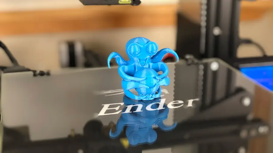
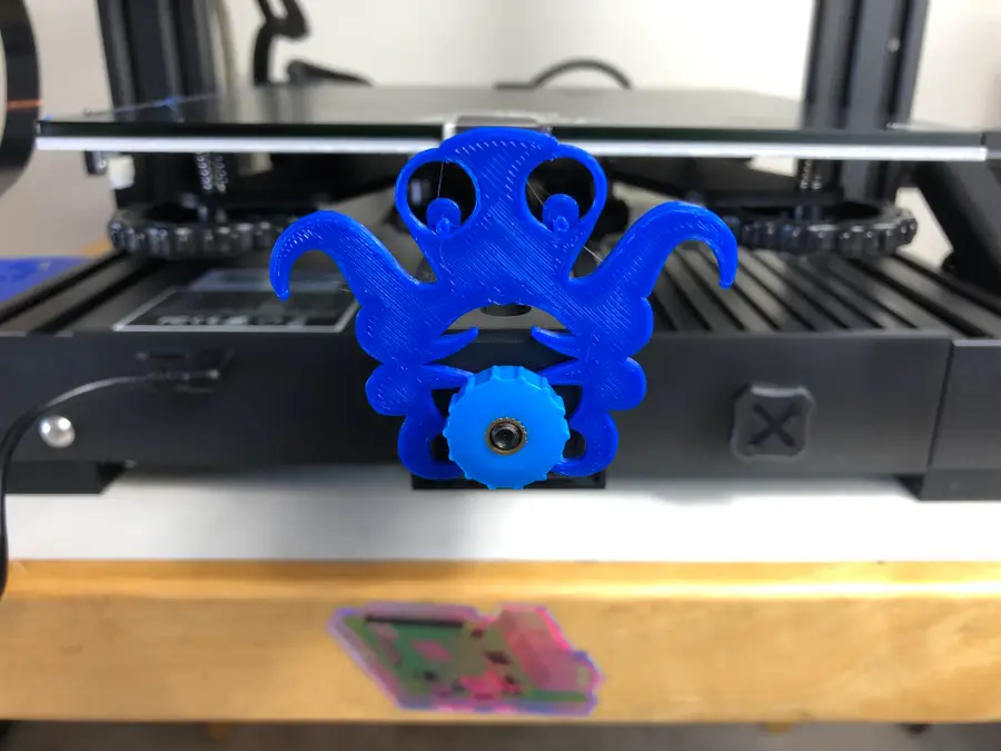
The Creality Ender 3 is amazing. The only thing that could make it more amazing is modding it so tha
With the release of the Creality Ender 3 V2, many of the Ender’s biggest fans who upgraded to
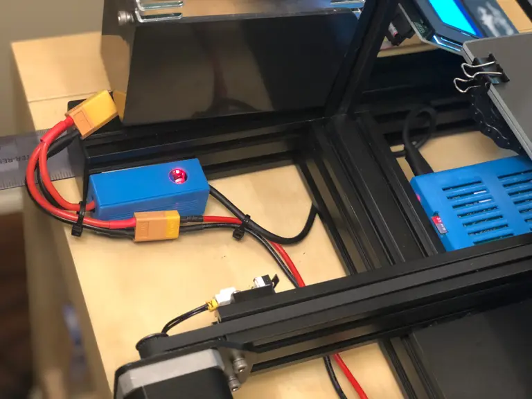
This guide will show you how to power a Raspberry Pi using your 3D printer’s power supply. Thi
This guide will show you how to add a touchscreen to any 3D printer for use with OctoPrint, a popula

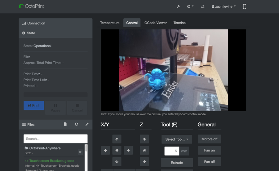
1 – What is OctoPrint? OctoPrint is 3D printing software. You install it onto a computer, typ
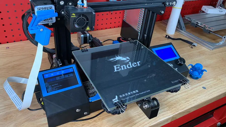
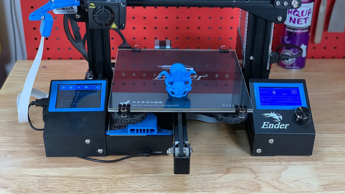
This guide will teach you how to add a touchscreen to your Creality Ender 3 or Ender 3 Pro for use w

OctoPrint is an incredibly useful tool for any 3D printer owner. Setting it up is easy, just follow
This short guide will show you how to update or upgrade OctoPrint and OctoPi on your Raspberry Pi. U