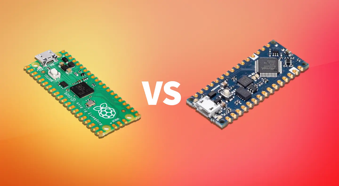
Finding the right microcontroller for your project is critical for not just budgetary reasons but al
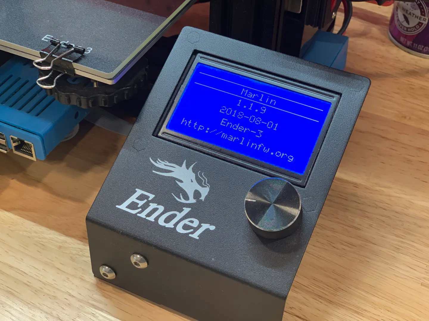
This guide will show you how to install a bootloader and update the Marlin firmware on your Ender 3
Explore Howchoo's most popular interests.