
Blender is one of the most popular open-source 3D creation suites today. It doesn’t cost a dim
Blender has made a name for itself over the years as the go-to open source 3D modeling application.
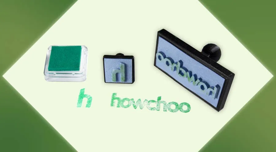
Let’s make some stamps! Why bother buying a pre-made design when you can create one yourself?
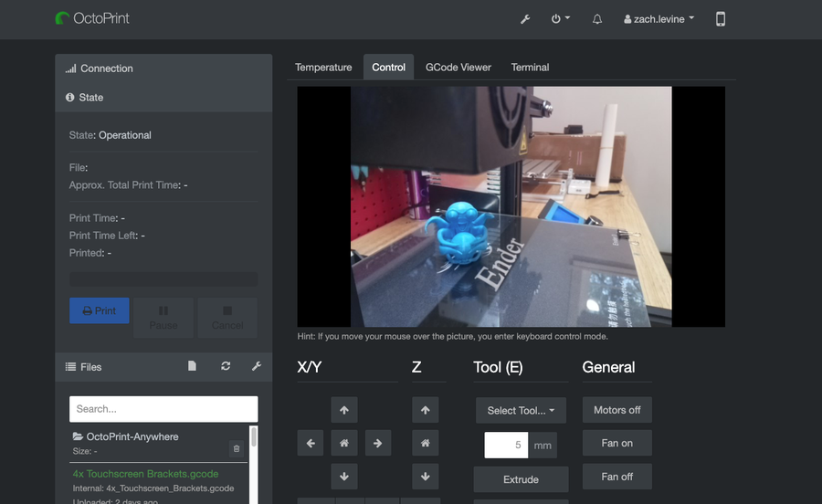
Like dark themes? Me too! This short guide will show you how to add a dark theme to your OctoPrint�
If you’re like me and are just starting out on your 3D printing journey, there’s little doubt in
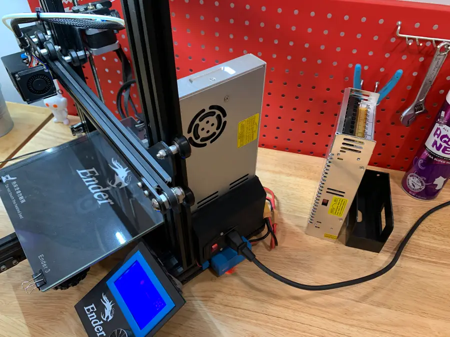
Aside from upgrading your Ender 3 board, upgrading your stock PSU to a Mean Well PSU is one of
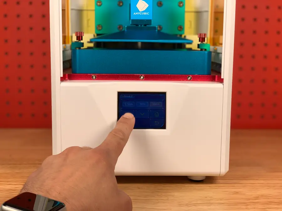
This guide will show you how to use your Anycubic Photon or Photon S. I’ll walk you through th
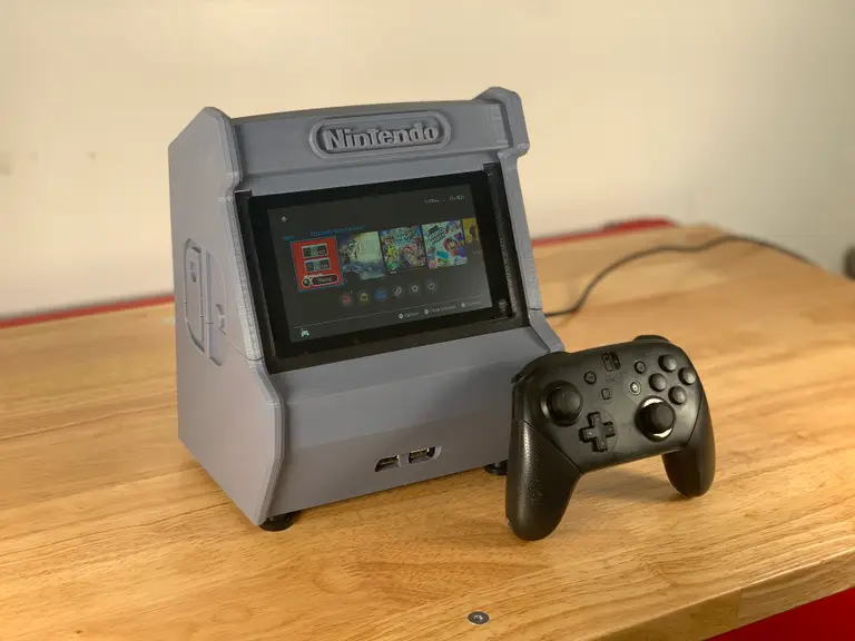
Today I’m going to show you how to build your own 3D-printed Nintendo Switch arcade cabinet! S

OctoPrint is a platform designed for the Raspberry Pi that makes it possible to monitor and control
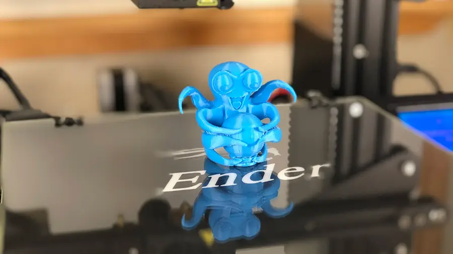
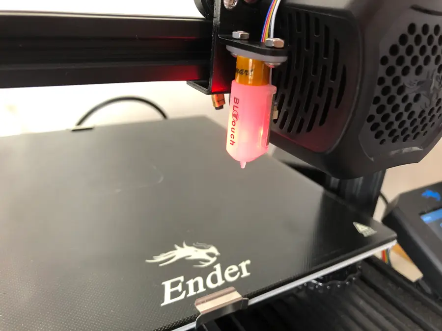
The Creality Ender 3 is amazing. The only thing that could make it more amazing is modding it so tha
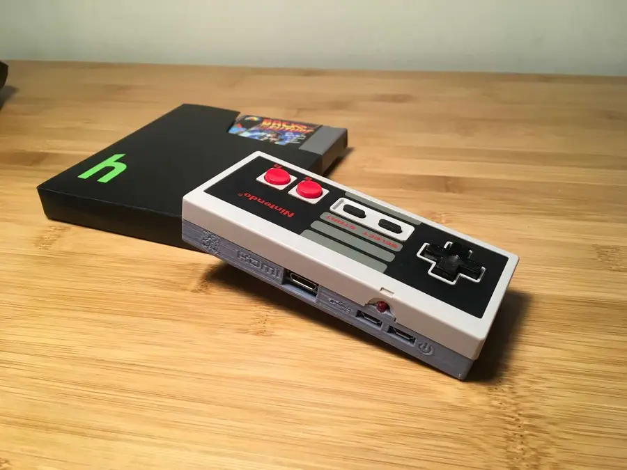
What’s cooler than running all your favorite emulated games on a $10 computer? Putting that co
Remember the days when you found yourself hunkered down over your Ender 3, Ender 3 V2, or Ender 3 Pr