Build a Simple Raspberry Pi LED Power/Status Indicator


Share
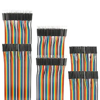
What you'll need
Interests


Posted in these interests:

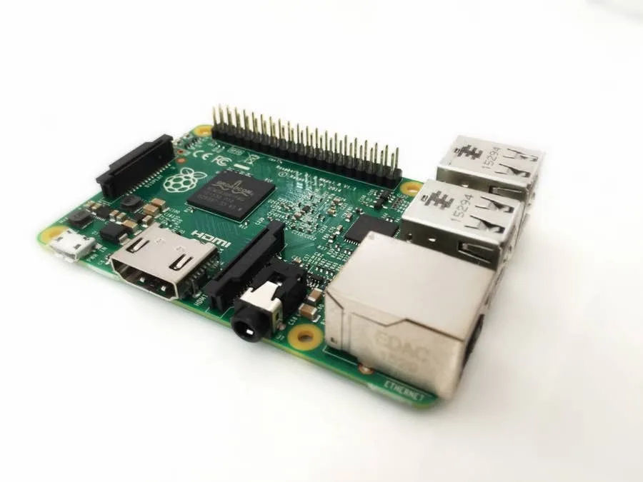
This short guide will show you how to add an LED power indicator/status light to your Raspberry Pi, letting you know when it’s powered and when it’s safe to unplug your Pi. This LED will illuminate when your Pi is running and turn off when your Pi has been successfully shut down. The LED can then be mounted anywhere on your project—for example, on the outside of your PiCart’s NES cartridge/case.
This guide will work with any Raspberry Pi model/version. In addition to the full guide below, I also made a Raspberry Pi power LED video version of this guide:
Be sure to check out both!
1 – Why is this useful?
There are several reasons a power LED is useful:
You left your Pi on
This LED will remind you to turn it off.
Your Pi is safe to unplug
It’s unsafe to shut down your Raspberry Pi by pulling the plug since this can lead to data corruption. However, after shutting your Pi down safely, this LED will tell you when it’s safe to pull the plug.

2 – Don’t Pull the Plug: How to Safely Shut Down or Reboot Your Raspberry Pi
There are a few basic methods for illuminating LEDs on your Pi:
1. Software approach:
The LED is connected to one of your Pi’s GPIO (general-purpose input/output) pins and you write a bit of code that will monitor and update the LED based on some input—for example, your Pi running or the temperature outside being higher than 76 degrees.
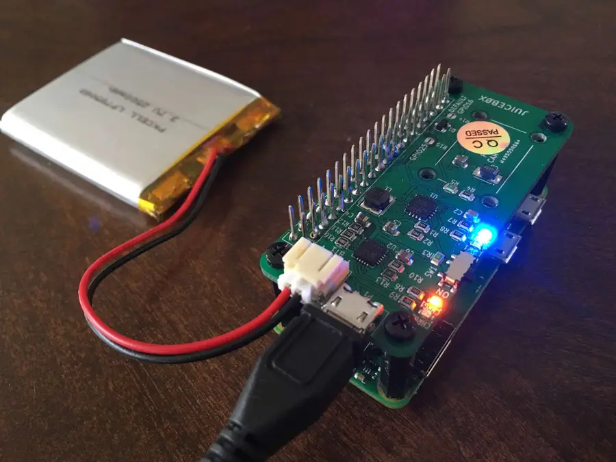
Pros: You can illuminate LEDs of various colors, or illuminate your LED based on dynamic input—such as when a battery-powered Pi is running low on juice.
Cons: Requires you to write software that executes at startup, adding a bit of complexity.
2. Serial approach (this guide):
The LED Is connected to your Pi’s TxD pin, which monitors the serial console. The LED will flicker a tad while booting, stay solid while your Pi is running, and turn off when it’s safe to remove power.
Pros: Simplicity. No code is needed and it just sort of works. Also, this is a great foray into the hardware portion of your Pi.
Cons: Limited to providing information about when the Pi is on or off—a very binary solution.
3 – Enable the GPIO serial port
Newer versions of Raspberry Pi OS (May 2016 and later) have the GPIO serial port disabled by default; the end result is your LED will not light up! Luckily, enabling it is super easy.
Edit your /boot/config.txt file and add the following line:
enable_uart=1You can edit this file by connecting to your Pi via SSH or by putting the SD card into your computer and editing the file directly. This file is accessible from the SD card.

How to Connect to a Raspberry Pi Remotely via SSH
The preferred (and most common) method of connecting to your Pi to run commands.
4 – Build the LED circuit
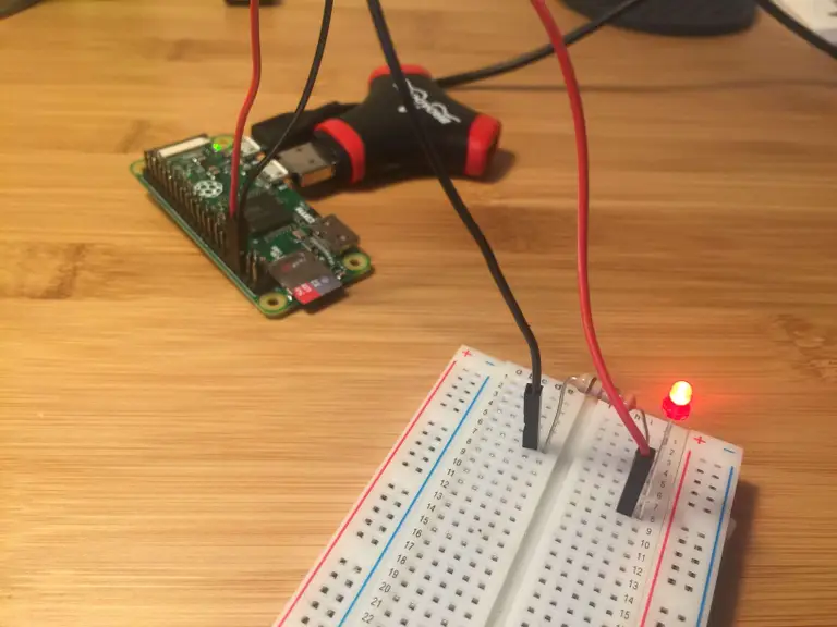
This step will require some soldering. I rigged everything up on a breadboard to prototype, but you can go straight to soldering now that we have the circuit figured out.
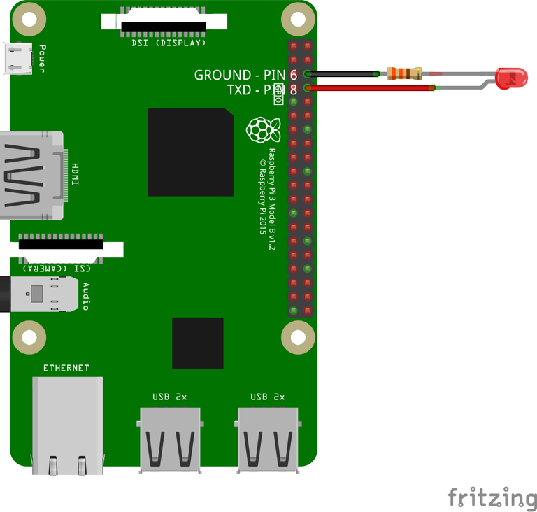
To build this circuit, we’re going to use a 330Ω (ohm) resistor connected to a small LED (about 2V, but one of slightly higher voltage will work well too—just keep it below 5V). The LED is powered by the Pi’s TxD serial output pin and the resistor protects the Pi against your LED requesting high current draws that can fry your Pi.
The LED’s “short” (negative/cathode) lead connects to the resistor and your Pi’s ground pin, while the “long” (positive/anode) lead connects to the TxD pin.
Use the attached circuit diagram to solder your connections. If you’re using a Pi Zero and don’t have header pins soldered to your Raspberry Pi, you can solder directly to the Pi itself. Remove your SD card before soldering to your Pi as it is easily damaged by heat. Be sure to leave enough wire for your LED to reach its final destination.
Pinout.xyz is a great resource for learning about and identifying your Pi’s GPIO pins.
If something is already connected to your Pi’s ground on pin 6, you can use any other ground pin on your Pi. You can see a list of other GPIO ground pins here.
| 🛈 Blue or white LEDs may not illuminate property as they draw more current and the Pi’s pins may be unable to supply it. |
5 – Test the LED circuit
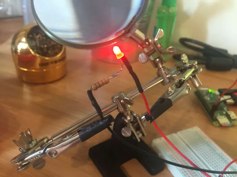
Boot up your Pi—the LED should illuminate solid once fully booted. Next, safely shut down your Pi and after several seconds the LED should turn off.
| 🛈 You can see I’ve added some heat wrap to my connections to insulate them a bit—this is purely optional. |
6 – Install the LED circuit
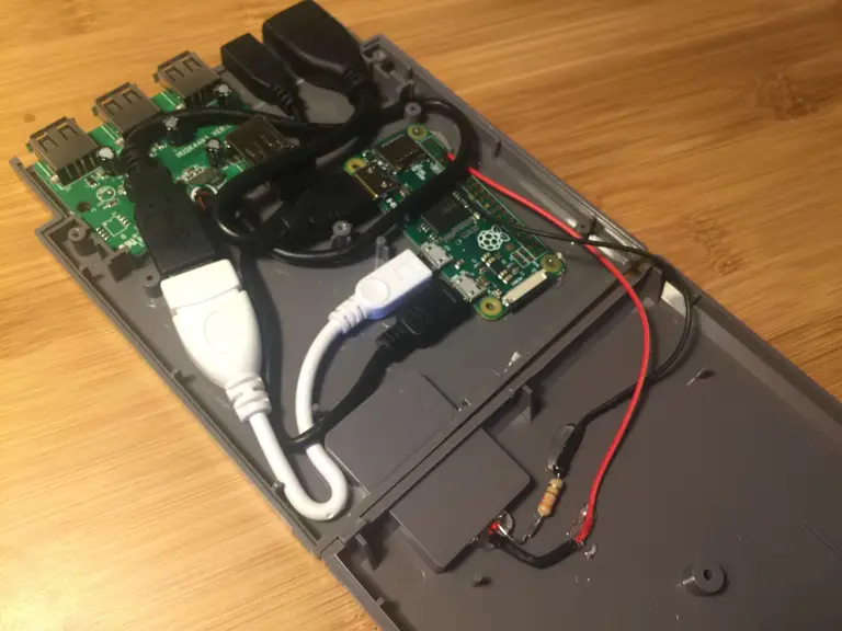
Now for the fun part: installing the LED in your case. I used a small drill bit and installed the LED just beneath the thumb-hold on my Pi Cart so that it would illuminate the table just beneath the cartridge.

| 🛈 Notice in this photo I forgot to put my SD card back in. Don’t do that. 🙂 |
7 – Circuit powered off

Here’s a shot of the status LED after the Pi has been powered off. This also shows the installation location I chose. I used a 3mm drill bit to install the LED.
| 🛈 Now I know it’s safe to unplug my Pi! |
8 – All finished!

Here’s the final product. Works great! If you have any comments or questions, post below and I’ll do my best to help you out.
| 🛈 That was simple, eh? |
9 – Combining a power button and power LED
Next, add a power button to your Raspberry Pi and shut it down safely! The power button will even wake your Pi up. You can even use an illuminated button by combining the fundamentals from this LED guide and the power button guide. 🙂

How to Add a Power Button to Your Raspberry Pi
Because you should always safely shut down your Pi.