
There are several ways to go about running a Minecraft server on the Raspberry Pi. In this guide, I&
With summer right around the corner, it’s time to fire up the grill! But who will watch the gr
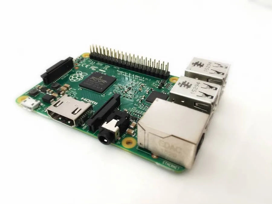
So you just got your brand new Raspberry Pi. Awesome! This guide will show you how to set up a brand
You’ve put so much work into setting up RetroPie or EmulationStation. You load it up
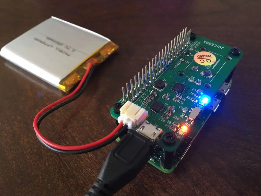
The Raspberry Pi Zero is an incredible tool for building a wide variety of IoT devices. And until la
There are many reasons you may want to connect your Raspberry Pi to your computer, and there are a f
Home automation is growing in popularity, but one of the biggest hurdles is compatibility betwe
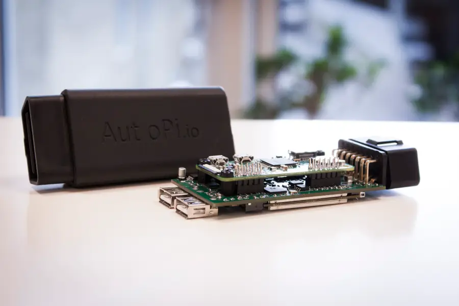
Have you ever wanted to add an entertainment system to your car, only to find that most units are ex
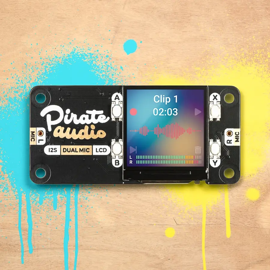
There are so many cool HAT extensions for the Raspberry Pi to make your next project literally sing
OctoPrint is a platform designed for the Raspberry Pi that makes it possible to monitor and control
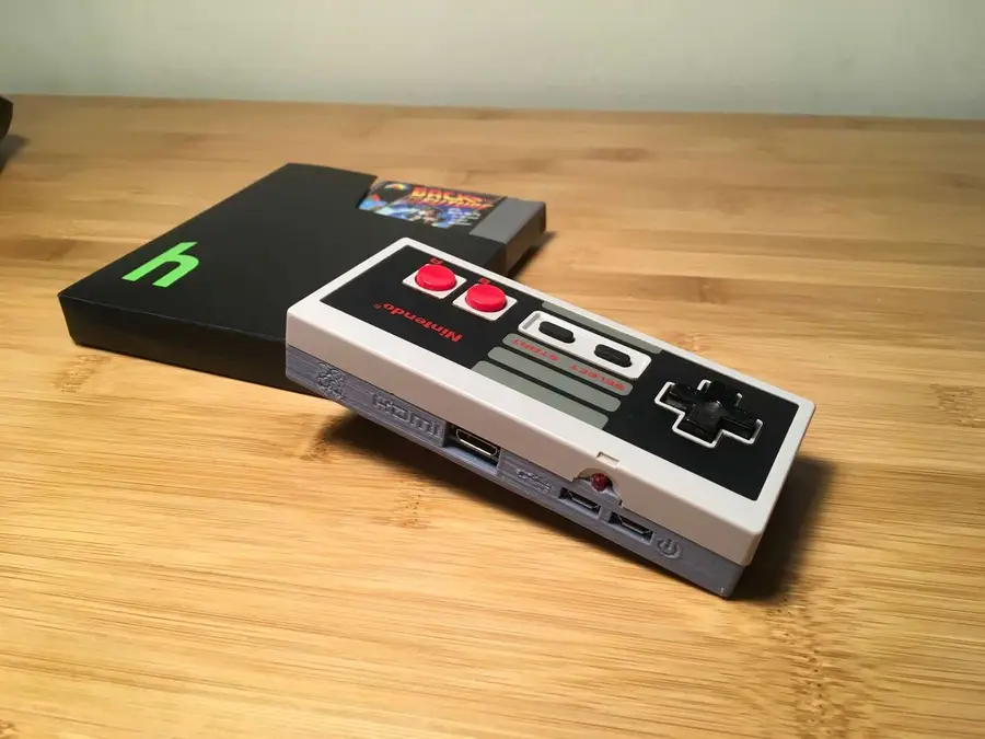
What’s cooler than running all your favorite emulated games on a $10 computer? Putting that co
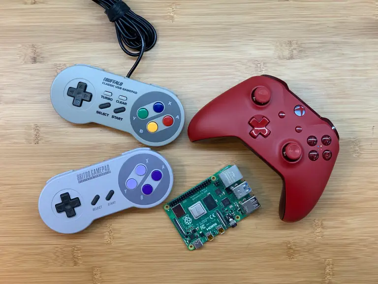
If you want to play retro games on RetroPie, you need a controller. But not all controllers are crea